Welcome to the 2GNT Forum! Interested In Advertising with 2GNT?
Home | Site Background| Info&Specs| Mods & Tech Info | CAPS | Part Reviews | Donate | 2GNT Stickers |
Search Printer-friendly copy Email this topic to a friend 0 Users in Chat
Top 2GNT Technical Turbo/Nitrous Tech topic #108509
View in linear mode

Subject: "RE: Challenge: plot your setup on the compressor map" Previous topic | Next topic
AdministratorCODE4Feb-17-11 06:51 PM
Member since Nov 23rd 2003
2552 posts,
Click to send email to this author Click to send private message to this author Click to view this author's profile Click to add this author to your buddy list
#108522, "RE: Challenge: plot your setup on the compressor map"
In response to In response to 7
Feb-17-11 07:03 PM by CODE4


Originally posted by Slo2g
Maybe Dave, although I don't see how(don't know what I did wrong). I used 18psi and I actually used 420hp but it should be more(I was going off what my car actually made on the dyno and not crank hp.) I'm awaiting your responce


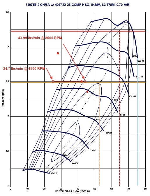
***Annotated worksheet in first post to make the different calculations clearer. Plotting points on compressor map with known boost pressure requires the last equations only!***

Zac, I think the confusion stemmed from my calculation example. Really, to plot the mass air flow all one needs to do is use the last equation to solve for Mass Air Flow. The MAP psia is Manifold Pressure + System Loss (I used 2 psi for this example) + atmosphere (14.7). The pressure ratio should be the same across different RPM points, unless of course boost creep is happening or you have a 2 stage boost controller.

AirFlow(actual) = ((MAP psia) * VE * (N/2) * Displacement) / (639.6 * (460 + IM Temp))

MAP psia = (Manifold Pressure) + (Atmosphere) + (system loss)

MAP psia = 18 + 14.7 + 2 = 34.7 psia

Pressure Ratio = (MAP + Pressure Loss) / (Compressor Inlet Pressure - Pressure Loss Due to Filter)

Pressure Ratio = 34.7 / 13.7

Pressure Ratio = 2.53

AirFlow(actual) = (34.7 * 0.98 * 2250 * 122.04) / (639.6 * 590)

AirFlow(actual) = 9337707.54 / 377364

AirFlow(actual) = 24.7 lbs/min @ 4500 RPM

AirFlow(actual) = 43.99 lbs/min @ 8000 RPM


---

2012 2500HD LML


Report This Post to Admin Printer-friendly copy | Reply | Reply with quote

Challenge: plot your setup on the compressor map [View all] , AdministratorCODE4, Feb-12-11 10:02 PM
  RE: Challenge: plot your setup on the compressor map, Global Ruler Of All ThingsDarkOne, Feb-12-11 11:31 PM, #1
RE: Challenge: plot your setup on the compressor map, Slo2g, Feb-12-11 11:43 PM, #2
      RE: Challenge: plot your setup on the compressor map, AdministratorCODE4, Feb-13-11 07:40 PM, #3
           RE: Challenge: plot your setup on the compressor map, Slo2g, Feb-16-11 09:59 PM, #4
                RE: Challenge: plot your setup on the compressor map, 420agreenvilleSC, Feb-17-11 08:31 AM, #5
                RE: Challenge: plot your setup on the compressor map, AdministratorCODE4, Feb-17-11 09:03 AM, #6
                     RE: Challenge: plot your setup on the compressor map, Slo2g, Feb-17-11 12:09 PM, #7
                          RE: Challenge: plot your setup on the compressor map, AdministratorCODE4, Feb-17-11 06:51 PM #8
How To Read Turbo Compressor Map | Explained, AdministratorCODE4, Feb-17-11 07:51 PM, #9
RE: How To Read Turbo Compressor Map | Explained, 420agreenvilleSC, Feb-18-11 08:02 AM, #10
      RE: How To Read Turbo Compressor Map | Explained, Slo2g, Feb-18-11 08:30 AM, #11
           RE: How To Read Turbo Compressor Map | Explained, AdministratorCODE4, Feb-18-11 01:34 PM, #12
                RE: How To Read Turbo Compressor Map | Explained, Slo2g, Feb-18-11 01:48 PM, #13

Top 2GNT Technical Turbo/Nitrous Tech topic #108509 Previous topic | Next topic
Powered by DCForum+ Version 1.2
Copyright 1997-2003 DCScripts.com

I generated this page in 0.043056964874268 seconds, executing 12 queries.