|
Originally posted by streetlightning
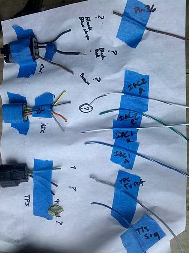
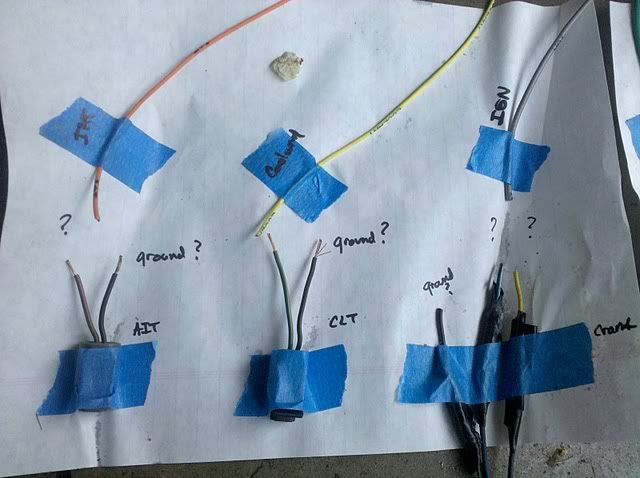
Crank
Pin 1: Yello 8v Refernce ------5 Volts Vref from Ms
Pin 2: Black /Green- ground ---GROUND
Pin 3: Blue whgiite: signal---- IGN from Ms (shielded wire)
Correct.
Originally posted by streetlightning
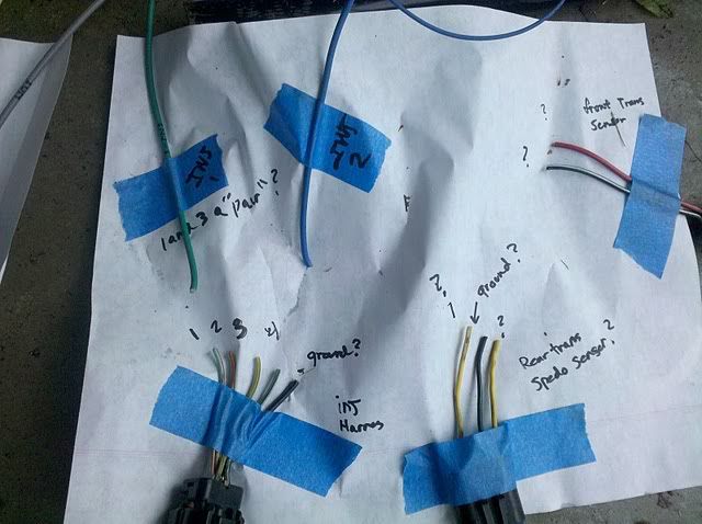
VSS:
Yellow: 8v Refernce ------5 Volts Vref from Ms
Black /green - ground ---GROUND
Yellow/white tach signal ---goes under dash to white tach wire
The VSS shouldn't be providing a signal to the tachometer, it should only provide a signal to the speedometer. Modify your schemata so this wire connects to the yellow/white wire under the dash.
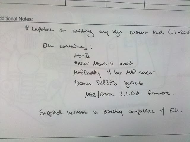
In the pictures of the documentation you have, there's no indication your Megasquirt ECU has a specific tachometer output circuit. You will either have to have one added, or you can use a GPO, but you may (or may not) have to add a 1k ohm pullup resistor. Then, connect the appropriate wire in your Megasquirt ECU's harness to the white wire under the dash.
Originally posted by streetlightning
TPS
BROWN / RED- Signal ----tPS SIGNAL ON ms
Green yellow- 5v power ------5 Volts Vref from Ms
Correct, but this sensor also needs to be grounded... the wire is black/green.
Originally posted by streetlightning
cOIL:
BROWN: coil 2-4 -----brown wire on Ms
BLack/blue Coils 1/3 -----green / white stripe wire on Ms
Black red - 12V or ASD relay. ----12 V or wire this to the ASD relay ill have to build?
It says brown on ms diagram to coil 2-3, shouldnt it be, 2-4? and same for the other wire, where it says 1-4, shouldn't it be 1-3?
Piston's one and four are at top dead center while pistons two and three are at bottom dead center. The documentation you have is correct and your assumption is incorrect. If you modify your schemata to match the documentation, this portion will be correct.
Originally posted by streetlightning
IAC
this one idk, shouldnt there be a power and ground? or is this just resistance based?
Green / Blue Iac pin 2
Orange/blue Iac pin 3
The 2G N/T DSM IAC has four connections, none of which are explicitly for power or ground. Like the tachometer output, the documentation you have does not indicate your Megasquirt ECU has the stepper motor IAC circuit installed. It may be possible to have this circuit installed, but judging by everything else you have installed, it doesn't look like there's much room for it.
-----------------------------------------
-Paul
Service Manuals and Guides
|