| Go back to previous topic | | Forum name | Engine Management Systems & Controllers | | Topic subject | wiring up MS | | Topic URL | https://forums.2gnt.com/dcboard.php?az=show_topic&forum=i54&topic_id=4891 |
4891, wiring up MS
Posted by streetlightning, May-23-10 06:11 PM
Hi guys im wiring up my Ms. As some back ground, i removed the ECU aand the entire stock harness. I plan to run tis as full stand alone. I have the symtech Voltage regulator as well. i labeld and cut the connectors off of the harness to solder onto my MS harness, and im looking for some info on wire colors, i figure i could make a nice
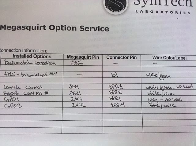
Heres the ms setup
![]() 
![]() 
I plan on using GPO1/2 for my fan/fuel and asd relays. is this a correct usage?
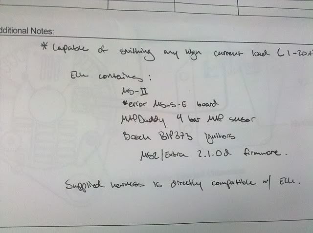
Heres a pic of a few connectors. THe ones with ? marks mean i dont know if they are signal or reqire 5V, and i take it the "5 v vref" is what i use to power the crank and other sensors that require a voltage source? i also dont have the other "pin 31" that goes to the coil? is that normal? or is my harness a little messed up?
I figure the black with green stripe is Grouns, correct?
![]() 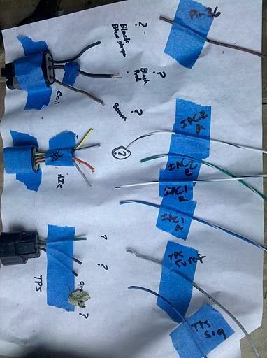
heres a pic of some more connectors.
are injecto 1 and 3 a pair? and do they belong to Inj 1 or inj 2.
As for the spedo sensor, which wire is signal, and which needs the 5v. and what do i connect the signal wire too? i dont see one on my harness. theres also a connector to the front of the trans, i dont think i need to do anything with that one? i think its my revers sensor?
![]() 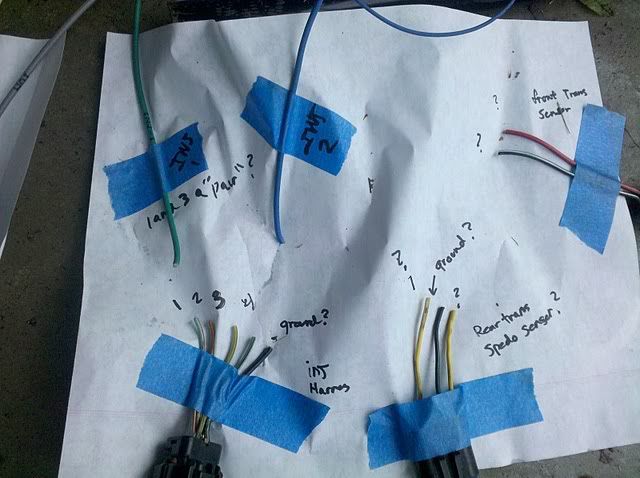
I think these are pretty simple, my ? here is on the crank sensor, which is signal, which needs voltage.
![]() 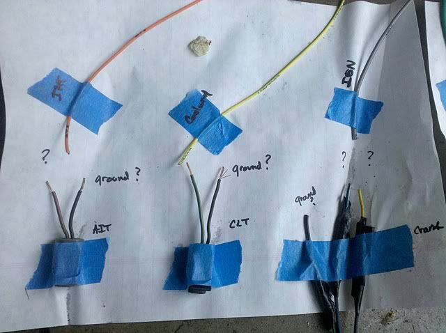
thanx for any help! its a 97 crank sensor, i know the 95/96 had a slightly differnt one or connector type.
|
4892, RE: wiring up MS
Posted by adamzty, May-24-10 08:21 AM
Originally posted by streetlightningi take it the "5 v vref" is what i use to power the crank and other sensors that require a voltage source?
Yes, that will work fine.
Originally posted by streetlightningi also dont have the other "pin 31" that goes to the coil? is that normal? or is my harness a little messed up? I figure the black with green stripe is Grouns, correct?
Where did you get your harness from? Wherever you got it from should have a wiring diagram for it, or at least a wire color chart.
Originally posted by streetlightningare injecto 1 and 3 a pair? and do they belong to Inj 1 or inj 2.
Injectors 1 and 3 are a pair wired to bank 1 on the MS. 2 and 4 are a pair wired to bank 2.
Originally posted by streetlightningAs for the spedo sensor, which wire is signal, and which needs the 5v. and what do i connect the signal wire too? i dont see one on my harness.
The signal wire will go straight to speedo wire under the dash. I forget what color that wire is, if I had access to the FSM I would look it up for you.
Originally posted by streetlightningtheres also a connector to the front of the trans, i dont think i need to do anything with that one? i think its my revers sensor?
Yes, reverse sensor. You will have to wire it to your reverse lights if you want them to work.
Originally posted by streetlightningI think these are pretty simple, my ? here is on the crank sensor, which is signal, which needs voltage.thanx for any help! its a 97 crank sensor, i know the 95/96 had a slightly differnt one or connector type.
I cannot see your pics here, they are blocked. The signal wire for the crank sensor is the blue/white one in the stock connector. I believe it's the middle pin. You may want to run a shielded wire here to get a better tach signal. The 2 outside pins are 5v and ground.
Good luck!
|
4893, RE: wiring up MS
Posted by 740 turbo brick, May-24-10 10:44 AM
The reverse lights will work on their own without any modification. As will the stock Coolant temp gauge and fuel level gauge.
|
4894, RE: wiring up MS
Posted by streetlightning, May-24-10 11:06 AM
thank you for the help! im sure ill have more ?S lol
as for harness, brand new from symtech.. so does it appear they may have forggoten to add the other wire for the coil?
|
4895, RE: wiring up MS
Posted by adamzty, May-24-10 02:58 PM
Originally posted by 740 turbo brick
The reverse lights will work on their own without any modification. As will the stock Coolant temp gauge and fuel level gauge.
Not if he removed the entire stock engine wiring harness. The fuel gauge will still work though.
|
4896, RE: wiring up MS
Posted by 740 turbo brick, May-24-10 10:18 PM
Hmm, good call I missed that part. You might be boned then. I was contemplating removing the entire harness. It would look clean but it was like 8 times more work involved.
|
4897, RE: wiring up MS
Posted by streetlightning, May-27-10 11:33 AM
i do have the pinout supplied by Symtech, but its missing the pin 31, it has pin 36, but no 31 and ive tried to call and email symtech to no avail.. i cant really wait around : ( should i add the pin myself?
symtech emaailed me back and said pin 31 is labeld IAC.. i have an iac 2 B, is this the right wire? the wires they call out state " pin 36 and pin 31" i have a brown wire labeld pin 36, so i figure there would be one that says pin 31...? they said the right wire might be green with a white stripe..? ne info
|
4898, RE: wiring up MS
Posted by streetlightning, May-29-10 01:14 AM
making some progress lol. as for the crank i dont have wires in it and i was searching on here but theres no clear refence to what pins = what..
so far i have the TPS, VSS, crank and iac to wire up..so if anyones got a pino out for those..that be great.
also since i have no stock harness, do i need to feed the TPS and Coil 12V? or a 5v refernce?
|
4899, RE: wiring up MS
Posted by streetlightning, May-30-10 01:50 PM
can some one verify
Crank
Pin 1: Yello 8v Refernce ------5 Volts Vref from Ms
Pin 2: Black /Green- ground ---GROUND
Pin 3: Blue whgiite: signal---- IGN from Ms (shielded wire)
VSS:
Yellow: 8v Refernce ------5 Volts Vref from Ms
Black /green - ground ---GROUND
Yellow/white tach signal ---goes under dash to white tach wire
TPS
BROWN / RED- Signal ----tPS SIGNAL ON ms
Green yellow- 5v power ------5 Volts Vref from Ms
cOIL:
BROWN: coil 2-4 -----brown wire on Ms
BLack/blue Coils 1/3 -----green / white stripe wire on Ms
Black red - 12V or ASD relay. ----12 V or wire this to the ASD relay ill have to build?
It says brown on ms diagram to coil 2-3, shouldnt it be, 2-4? and same for the other wire, where it says 1-4, shouldn't it be 1-3?
IAC
this one idk, shouldnt there be a power and ground? or is this just resistance based?
Green / Blue Iac pin 2
Orange/blue Iac pin 3
|
4903, RE: wiring up MS
Posted by streetlightning, Jun-02-10 10:55 PM
Can anyone help me verify its wired correctly?
Can i use one relay triggerd off ignition to power my alt, ms, fuel pump, injector 12v and coil 12v?
|
4905, RE: wiring up MS
Posted by VelocitaPaola, Jun-03-10 08:17 AM
Originally posted by streetlightning
Can i use one relay triggerd off ignition to power my alt, ms, fuel pump, injector 12v and coil 12v?
Your Megasquirt ECU should be activating the ASD relay. It can't activate this relay if it's also powered by it!
Since you removed the stock harness and you seem a little confused about its structure, perhaps you should review the stock wiring diagrams before proceeding. Click the link in my signature line to download a copy of the FSM's electrical guide.
|
4906, RE: wiring up MS
Posted by streetlightning, Jun-03-10 08:41 AM
i dont have a stock harness anymore, i removed everything, which means any stock relays. My asd and other relay next to it are gone. i see normally when keeping stock harness you tap into it there. but thats not the case here. lol re -read ur post, i guess u get that lol.
ive looked over and over at the fsm, and its not clear, as i was trying to figure out what wires on what sensors did what. ill look at yours, perhaps its clearer..
i figured id wire a relay for Ms, another for fuel pump, and another for the alt/fiel is that correct?
I thought my relays would be triggerd by ignition to turn on the MS, alt and supply the 12v to the fuel pump, inj harness and coil.
as for IAC, i have the Fidle, option, does that relate to my Iac?
**your fsm tells me theirs an error..?
as for the tach, i thought it got the signal from the crank sensor? shit i thought this was a complete unit and needed no more mods when i sent it out to you guys : (
**
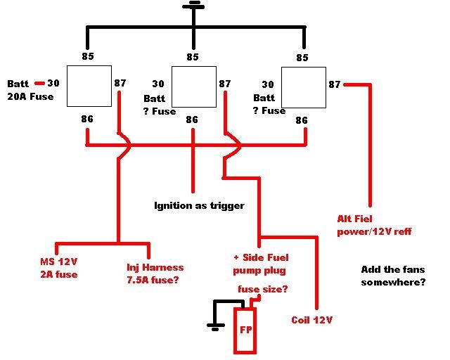
Here are the wires I have that need power I guess, and I thought would be triggerd by Ign via relay
*Injectors (since its one power line instead of 2, should I run 7.5A instead of 5A?
*Coil plug (will this need to be fused and at what amperage?)
*Alt Fiel
*Fuel pump- I have this wired up so its basically doing the “re-wire” mod, with the exception of my ignition would be triggering the pump on, is that correct? (will this need to be fused and at what amperage?)
*Ms needs power 2a fuse.
*Fans? Keep in mind these are pretty basic aftermarket fans, just a 12V and ground hook up.
this is whats in my head? am i a retard?
![]() 
|
4908, RE: wiring up MS
Posted by VelocitaPaola, Jun-03-10 10:37 PM
Originally posted by streetlightningi figured id wire a relay for Ms, another for fuel pump, and another for the alt/fiel is that correct? I thought my relays would be triggerd by ignition to turn on the MS, alt and supply the 12v to the fuel pump, inj harness and coil.
You're starting from scratch, so you can either attempt to recreate the stock wiring harness by studying the FSM, or you can review all the suggestions in the MegaManual. The MegaManual was written with retrofitting older vehicles without any sort of EFI system (and wiring harness) in mind, so the same basic principles apply to your installation:
http://www.megamanual.com/ms2/V3assemble.htm#ew
Originally posted by streetlightningas for IAC, i have the Fidle, option, does that relate to my Iac?
You can install a fast idle air valve (FIDLE) that sinks up to 1A on that wire, but not your stock stepper motor IAC.
Originally posted by streetlightningas for the tach, i thought it got the signal from the crank sensor?
The tachometer receives its signal from the stock PCM, or a tachometer output circuit in a Megasquirt ECU. It does not receive its signal from the crankshaft angle sensor.
Originally posted by streetlightningshit i thought this was a complete unit and needed no more mods when i sent it out to you guys : (
I'm not exactly sure what you mean, but it looks like you had work done to this ECU. All the options can be overwhelming, but there are packages out there specifically for Megasquirt users wanting to completely remove the stock PCM, such as yourself.
Originally posted by streetlightning** Here are the wires I have that need power I guess, and I thought would be triggerd by Ign via relay *Injectors (since its one power line instead of 2, should I run 7.5A instead of 5A? *Coil plug (will this need to be fused and at what amperage?) *Alt Fiel *Fuel pump- I have this wired up so its basically doing the “re-wire” mod, with the exception of my ignition would be triggering the pump on, is that correct? (will this need to be fused and at what amperage?) *Ms needs power 2a fuse. *Fans? Keep in mind these are pretty basic aftermarket fans, just a 12V and ground hook up. this is whats in my head? am i a retard?
See above.
|
4910, RE: wiring up MS
Posted by streetlightning, Jun-04-10 10:19 AM
the relay info i have i have addapted from reading on Mega manual and the schematics that are floating, butim not that confident, so i guess i was lloking for a yes that looks correct lol.
As for when i had it serviced, i thought having the tach work was standard. unfortunalty this opens up more issues for me. i bought this unit of a member here that tach was working on, and it had been modded according to the sticky "no tach spikes" ect, so im a little conffused on why i wont have a tach signal if this was modded for one. when i sent it to have a diagnostic run, was anything removed?
and since theres not alot of room left, what are my optins for getting a tach signal?
Ill be blunt, the FSM has a lot of sweet info, but reading the eltrical readouts is murder. i like how some connectors have nice pin outs, what whires where and what they do , others good luck. Ive been looking at the fsm for 2 weeks trying to awnser my own ?s and im still not getting all the awncers i needed, not trying to come off as a jerk, but ive really tried to be as independant as i can with researching lol.
i know not a ton of 2gnts have gone the route of removing everything, but i hope its understandable that im a little flustrated. i really wanted to put something to gether for anyone esle doing this ie a nice wiring diagram and lay out, but this is hurting my head lol. i just want to get my car running so i can play..
on the MS 3 wiring diagram in that link, the fuel pump relay has a wire going into the db37 connector, is that the fuel pump wire? is that wire grounded? or will that "fuel pump" wire be my trigger instead of the ignition?
|
4911, RE: wiring up MS
Posted by VelocitaPaola, Jun-04-10 01:29 PM
Originally posted by streetlightning
the relay info i have i have addapted from reading on Mega manual and the schematics that are floating, butim not that confident, so i guess i was lloking for a yes that looks correct lol.
No, it doesn't look correct.
Your Megasquirt ECU should be switching at least a fuel pump relay and an ASD relay, but possibly a fan control relay as well. The Megasquirt ECU should be receiving its switched +12V power directly from the ignition switch.
Originally posted by streetlightningAs for when i had it serviced, i thought having the tach work was standard. unfortunalty this opens up more issues for me. i bought this unit of a member here that tach was working on, and it had been modded according to the sticky "no tach spikes" ect, so im a little conffused on why i wont have a tach signal if this was modded for one. when i sent it to have a diagnostic run, was anything removed? and since theres not alot of room left, what are my optins for getting a tach signal?
I don't know the specifics of your ECU, I'm just basing my comments on the pictures you posted.
"No tach spikes" indicates the ECU will more consistently read the signal from the crankshaft angle sensor; it has nothing to do with providing a signal to the tachometer. Like I said, you should be able to use a GPO as a tachometer signal source, you just might have to add a 1k ohm pullup resistor (this can be done internally or externally).
Originally posted by streetlightningIll be blunt, the FSM has a lot of sweet info, but reading the eltrical readouts is murder. i like how some connectors have nice pin outs, what whires where and what they do , others good luck. Ive been looking at the fsm for 2 weeks trying to awnser my own ?s and im still not getting all the awncers i needed, not trying to come off as a jerk, but ive really tried to be as independant as i can with researching lol.
Most all of the information you need is in the FSM. I understand it can be confusing if you're not accustomed to automotive electrical schematics. Don't just stare at them hoping something will "click," read the information at the beginning of the circuit diagrams section. The diagrams contain everything from connection information and connector pin assignments to wire colors.
Originally posted by streetlightningon the MS 3 wiring diagram in that link, the fuel pump relay has a wire going into the db37 connector, is that the fuel pump wire?
Yes.
Originally posted by streetlightningis that wire grounded?
Yes.
Originally posted by streetlightningor will that "fuel pump" wire be my trigger instead of the ignition?
I'm unsure what you mean. Your Megasquirt ECU will provide the relay a path to ground when necessary (i.e. whenever it reads a signal from the crankshaft angle sensor, and once upon power-up to prime the fuel system).
|
4912, RE: wiring up MS
Posted by streetlightning, Jun-04-10 02:08 PM
ok, that helped a lot, it makes sence if the fuel pump wire goes to ground. and ill use the fule pump wire as "ground" for the asd and fuel pump realys that way the ms is controling them. as for the tach , i have 2 gpo's i beilve so ill investage what it will take to get that working as a fan control and Tach signal.
this is more like what you are showing/saying?
![]() 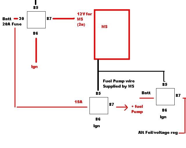
15amp should go inline with fuel pump, i placed it wrong **
|
4913, RE: wiring up MS
Posted by streetlightning, Jun-04-10 05:50 PM
Also...what size fuse would be suggested for the coils 12v and the supply voltage for the alt relay will that need a fuse too? If so is there a size?
|
4904, RE: wiring up MS
Posted by VelocitaPaola, Jun-03-10 08:13 AM
Originally posted by streetlightning
Crank
Pin 1: Yello 8v Refernce ------5 Volts Vref from Ms
Pin 2: Black /Green- ground ---GROUND
Pin 3: Blue whgiite: signal---- IGN from Ms (shielded wire)
Correct.
Originally posted by streetlightning
VSS:
Yellow: 8v Refernce ------5 Volts Vref from Ms
Black /green - ground ---GROUND
Yellow/white tach signal ---goes under dash to white tach wire
The VSS shouldn't be providing a signal to the tachometer, it should only provide a signal to the speedometer. Modify your schemata so this wire connects to the yellow/white wire under the dash.
In the pictures of the documentation you have, there's no indication your Megasquirt ECU has a specific tachometer output circuit. You will either have to have one added, or you can use a GPO, but you may (or may not) have to add a 1k ohm pullup resistor. Then, connect the appropriate wire in your Megasquirt ECU's harness to the white wire under the dash.
Originally posted by streetlightning
TPS
BROWN / RED- Signal ----tPS SIGNAL ON ms
Green yellow- 5v power ------5 Volts Vref from Ms
Correct, but this sensor also needs to be grounded... the wire is black/green.
Originally posted by streetlightning
cOIL:
BROWN: coil 2-4 -----brown wire on Ms
BLack/blue Coils 1/3 -----green / white stripe wire on Ms
Black red - 12V or ASD relay. ----12 V or wire this to the ASD relay ill have to build?
It says brown on ms diagram to coil 2-3, shouldnt it be, 2-4? and same for the other wire, where it says 1-4, shouldn't it be 1-3?
Piston's one and four are at top dead center while pistons two and three are at bottom dead center. The documentation you have is correct and your assumption is incorrect. If you modify your schemata to match the documentation, this portion will be correct.
Originally posted by streetlightning
IAC
this one idk, shouldnt there be a power and ground? or is this just resistance based?
Green / Blue Iac pin 2
Orange/blue Iac pin 3
The 2G N/T DSM IAC has four connections, none of which are explicitly for power or ground. Like the tachometer output, the documentation you have does not indicate your Megasquirt ECU has the stepper motor IAC circuit installed. It may be possible to have this circuit installed, but judging by everything else you have installed, it doesn't look like there's much room for it.
| |