#92526, "Two questions: General EFI regarding FMU and boosting, 3-dimensional map" Jan-03-06 07:40 PM by evotunedscc
I was looking through the internet a couple of nights ago trying to learn more about FMUs and found a page that provides quite a bit of information about efi but has me stumped at one part; just checking to see if any of you guys can help clear it up for me.
That's the link. The first paragraph under 'Basics' explains maintaining fuel pressure across the rail and compensating for vacuum and boost conditions. This part I understand.
On down the page there's a section titled, 'Fuel Management Units.' This is the part that confuses me. -In the paragraph mentioned above, it used an example of maintaining 40psi(40psi +/- 0psi boost/vacuum) fp across the rail. Now in this paragraph it says that with a 10:1 FMU at 6psi boost you would have 60psi fp. Is this a typo? Shouldn't it be 100psi fp <40psi + 60psi(for 6psi boost at 10:1)>??
I'm probably missing something here, but if anyone has time to read through this and clear it up for me I'd appreciate it.
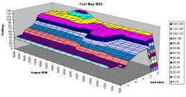
While I'm in the mood to ask a lot of questions, lol, can someone explain a 3-dimensional fuel map. I've heard of complex fuel management computers doing this, and I've reasearched it a little, but still dont understand.
On this site they refer to the x-axis as RPM ranges and the y-axis as Manifold Pressure. Now I'm really good in math, but I'm missing the z-axis here for this to be 3-dimensional.
I know this is a lot of stuff, but as soon as I get it cleared up I'll feel pretty good about myself.
#92527, "RE: General EFI question regarding FMU and boosting" In response to Reply # 0
Originally posted by evotunedscc I was looking through the internet a couple of nights ago trying to learn more about FMUs and found a page that provides quite a bit of information about efi but has me stumped at one part; just checking to see if any of you guys can help clear it up for me. http://home.att.net/~jroal/efi.html That's the link. The first paragraph under 'Basics' explains maintaining fuel pressure across the rail and compensating for vacuum and boost conditions. This part I understand. On down the page there's a section titled, 'Fuel Management Units.' This is the part that confuses me. -In the paragraph mentioned above, it used an example of maintaining 40psi(40psi +/- 0psi boost/vacuum) fp across the rail. Now in this paragraph it says that with a 10:1 FMU at 6psi boost you would have 60psi fp. Is this a typo? Shouldn't it be 100psi fp <40psi + 60psi(for 6psi boost at 10:1)>?? I'm probably missing something here, but if anyone has time to read through this and clear it up for me I'd appreciate it.
thats 60psi added to your static fuel pressure. so if your static was 40, at 6psi with a 10:1 regulator you'd have 100psi
-------------------- 99 GS-Turbo 3.55 MTX S16G @ ~15psi - FMIC - Forged Internals Clinton Township, MI
#92531, "RE: Two questions: General EFI regarding FMU and boosting, 3-dimensional map" In response to Reply # 0 Jan-04-06 04:09 AM by thedawg
Originally posted by evotunedscc can someone explain a 3-dimensional fuel map. I've heard of complex fuel management computers doing this, and I've reasearched it a little, but still dont understand. http://www.034motorsport.com/034ecu.html On this site they refer to the x-axis as RPM ranges and the y-axis as Manifold Pressure. Now I'm really good in math, but I'm missing the z-axis here for this to be 3-dimensional.
The Z-axis is your own fuel input settings.
So given a 2-D matrix of x=RPM and y=Manifold Pressure, then let z=User-specified fuel enrichment. Normally Z is controlled by a static "map" inside the stock ECU, and is not adjustable.
An example of "2-D" fuel mapping would be an SAFC where you can't control the fuel directly, so your settings only add or subtract percentages from the actual Manifold pressure value (Y) at each RPM (X) to trick the stock ECU into changing its fuel map.

 Search
 Printer-friendly copy
 2 Users in Chat