| Go back to previous topic | |
| Forum name | Turbo/Nitrous Tech |
| Topic subject | RE: Challenge: plot your setup on the compressor map |
| Topic URL | http://forums.2gnt.com/dcboard.php?az=show_topic&forum=8&topic_id=108509&mesg_id=108518 |
|
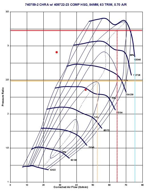
108518, RE: Challenge: plot your setup on the compressor map Posted by Slo2g, Dec-31-69 06:00 PM So I think I got it. I used the T04z compressor map because after some research( I could be wrong) I think this is the closest I could find to the S25g....any who here are my plots, the two red dots on the map. I used Dave's IAT's, pressure loss on intake and compressor outlet, and VE. This is also based off my 2.0 motor so its a 122.04 CI instead of Daves 2.4. | |