| Go back to previous topic | | Forum name | Performance/Engine | | Topic subject | Ideal LTH set up. | | Topic URL | https://forums.2gnt.com/dcboard.php?az=show_topic&forum=i5&topic_id=112693 |
112693, Ideal LTH set up.
Posted by DR1665, Apr-28-06 09:08 AM
I've been bumping this idea around for four months now (cough, cough), but get the feeling I'm talking to myself, so I'd like to get some outside thoughts on things.
I'm looking to install a custom, long tube header (LTH) on Daisy later this summer. With the Neon guys picking up 8-12whp with true, LTH systems, there's no reason why we should be limited to the old reliable Pacesetter or hey-look-at-me-I'm-not-concerned-with-value name brand headers currently on the market, so if this works out, I might actually have four or five like it up for sale for something like $500.
I've got a local all motor Neon guy willing to fab this thing up for me (mild steel, backpurged, ceramic coated), but we need to get the specs finalized so we can begin budgeting for supplies. Here's what I'm shooting for.
1 7/8" Primaries - 30" long into merge collector w/ 3" outlet. (4-1 design)
Yes. I said 3" outlet and I have a reason to go that route. If you have reason why I should not be going 3", you need to be able to back up why with solid information (ie; not just saying what you've seen around here).
I might cut the primaries back to 27-28", but this will eventually be the end of something that starts with quad TBs and winds out to somewhere around 9000rpm regularly. I'm trying to design a header that you can grow into which will provide real gains at the wheels.
Experienced/educated thoughts on primary sizing and length would be much appreciated. Any other relevant data (such as would pertain to exhaust gas pulse timing and measurement) would be appreciated as well.
Thanks for the read.
|
112694, RE: Ideal LTH set up.
Posted by BlackMagic, Apr-28-06 12:26 PM
Here is a graph relating overall torque in the powerband to primary pipe length. So it depends where you want your powerband.

|
112695, RE: Ideal LTH set up.
Posted by DR1665, Apr-28-06 02:04 PM
Thanks man. Reminds me of this one...

This chart applies to normally aspirated engines. For street headers, where low-speed torque is of prime importance (especially with a stock converter and high rear end gears), use the lower line to select the appropriate primary size. For hot street machines having reasonably big cams and decent compression, use the middle line to size the primary. For race engines, use the top line.
As you can see, I took the middle line, so I'd be looking to flow a shotload of exhaust. This is not going to be much of a daily driver.
|
112696, RE: Ideal LTH set up.
Posted by turbo8u, Apr-29-06 08:40 AM
make it out of stainless
i wouldnt go with a 3 inch outlet either. smaller outlet means more velocity...and thats what you want for the scavenging effect on the companion cylinders. small piping however creates backpressure at higher rpm's, so its a toss up. larger for more volume yes, but bigger is not always better. like you said though, "something to grow into"...so I don't know. why do you want/need a 3" outlet?
you're building it for low-end torque and daily drivability yes? go with a smaller outlet, in my opinion. maybe even use 1 5/8 tubing.
large ports you have already, combine that with large exhaust and you'll lose low end power. also, keeping the exhaust gas velocity high, it takes quite a bit more energy for exhaust gas to revert.
and remember:
velocity = CFM/area of piping
or if you don't know the exhaust gas cfm, plug in some numbers to this equation
CFM = (CuInDisplacement)x (full load rpm) x efficiency x exhaust gas temp +460) DIVIDED BY 2 x 941760
efficiency is going to something like .85 (85%) to .95 (95%) for your naturally ASSpirated motor :P
|
112697, RE: Ideal LTH set up.
Posted by BlackMagic, Apr-29-06 09:33 AM
Actually I'm pretty sure this is not going to be his daily driver. So I'm guessing he wants all the power up top where he can use it at the strip.
|
112698, RE: Ideal LTH set up.
Posted by DR1665, Apr-30-06 08:43 AM
Originally posted by BlackMagic
Actually I'm pretty sure this is not going to be his daily driver. So I'm guessing he wants all the power up top where he can use it at the strip.
Bingo. Only, not so much strip, but stage.
Originally posted by turbo8u
make it out of stainless
Heh. Eventually, but mild steel keeps prototyping costs down, bro. So long as the design is clean and the welds are tight inside and out, I'll be happy with it.
Originally posted by turbo8u
you said though, "something to grow into"...so I don't know. why do you want/need a 3" outlet? you're building it for low-end torque and daily drivability yes?
Something for other people to grow into. I plan on making full use of the high end breathing capabilities of this motor. Daisy's days of creeping through drive-thrus and rush hour traffic are numbered. Sure, she'll get out there from time to time; just for shits and giggles, but she's got other things in store. Back on the stock ECU since last August, I'm fairly familiar with the loss of power below 3500rpm. The next series of projects I want to try on the car are this LTH, C3s, ITBs, and finally weight reduction.
Originally posted by turbo8u
CFM = (CuInDisplacement)x (full load rpm) x efficiency x exhaust gas temp +460) DIVIDED BY 2 x 941760 efficiency is going to something like .85 (85%) to .95 (95%)
Heh. I think you need to double check the syntax on that one, turb.
Ex:
CFM = (<(123*9000*.90*1200)+460>/2)*941760
CFM = <(1,195,560,000+460)/2>*941760
CFM = (1,195,560,460/2)*941760
CFM = 597,780,230*941760
CFM = 562,965,509,404,800
She moves a lot of air, but I doubt she cycles three times the volume of the Earth's atmosphere every minute.
Now, supposing you meant to put parentheses around the last figure in the equation to be 4176, CFM would still come out to be just under half that ridiculous number above.
Of course, maybe you meant everything divided by (941760*2). That would make more sense, as it results in 634.75 (rounded to hundreths).
Originally posted by turbo8u
velocity = CFM/area of piping
Okay. Assuming the last figure was legit (since we're only playing with numbers at this point), velocity = 635/area^P? Shouldn't that be volume? Figure the volume of the header by calculating volume of all four runners plus the merge collector? Further figuring volume of entire exhaust system would allow ideal system paramaters, methinks. Got a target velocity? I don't want to get this deep into the subject although it would be cool to say I did.

en.wikipedia.org/wiki/De_Laval_nozzle#Exhaust_gas_velocity
I was thinking about ordering a book on the subject, but with all the reading I have to do for school, I don't think I'd actually finish it. Besides, a lot of this is hit-or-miss theory, anyway. I'd just like to come up with something that will do more good.
Originally posted by turbo8u
for your naturally ASSpirated motor :P
LMAO. Fast is relative, brother. When this bitch is done, she's going to be, and I say this in my best turby impression, siiiiiic.
More research will be done on this subject...
|
112699, RE: Ideal LTH set up.
Posted by Keith2172, Aug-24-06 01:16 PM
Just chiming in, is this primarily an open-header car, how much of an exhaust system are you actually going to run? And is this going to be 2.0 or 2.2 or 2.4 or 2.7?
|
112700, RE: Ideal LTH set up.
Posted by DR1665, Aug-25-06 04:20 AM
Originally posted by Keith2172
Just chiming in, is this primarily an open-header car, how much of an exhaust system are you actually going to run? And is this going to be 2.0 or 2.2 or 2.4 or 2.7?
This is a project in which I'm still interested. At the time I had made this post, I was planning on making Daisy a rally car and using the Galant for a nice daily driver, but I've since changed my mind. The Galant will become the rally car and Daisy will revert to reliable daily driver mode.
The header is still something I've been talking with Josh about doing. Ideally, it would be for 2.0L guys and available in limited quantities.
|
112701, RE: Ideal LTH set up.
Posted by turbo8u, Aug-25-06 09:45 AM
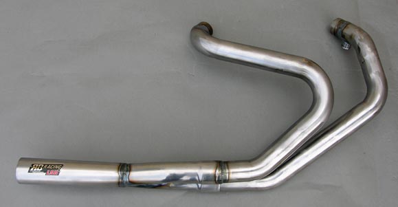
This is basically the design idea. I snapped this with my camera phone awhile back Brian.

Long tubes like this picture with the collector meeting the stock catalytic converter back past the oil pan. I could make something like this really easy out of stainless. 4 to 1, 4 to 2 to 1...whatever size tubing and wall thickness.
Driggs, hows .035 wall 304 stainless 1.5" primaries sound? 1.5" to small? I dont know. 18" long each, longer? 1/2" flange at the head, maybe 3/8". just give me details and lets get this shit made real quick and see how it likes Daisy.
edit: one question- since the firing order is 1342, running mates would be 1/4 and 3/2?
Originally posted by DR1665
velocity = 635/area^P? Shouldn't that be volume?
no the 635 you have there is the volume, CFM is the volume not the velocity. you need the volume, and how much space its in....to determine how fast its going (approximately)
Originally posted by DR1665
above. Of course, maybe you meant everything divided by (941760*2). That would make more sense
yea exactly what I meant. Hard to write an equation on here...I can tell you're not exactly a math whiz though lol!
Originally posted by DR1665"Got a target velocity?
hard to say, you'd want the fastest velocity and the lowest back pressure...a happy medium. good velocity, good air flow...the only way you could do that though, is with our equation (approximated) and your car running and back pressure being read off the exhaust. R&D...trial and error, and the dyno. however, most all harleys are designed to flow 300 ft/min and thats with 1 3/4 primaries. something to think about.
anyway, here let me set something up for you using that same equation and stock 420a specs, NA with a given 85% efficiency:
CFM (VOLUME NOT VELOCITY) = (121.8 cu in.) X 4800rpm (max torque, max intake air speed, max load, highest BSFC) X .85% NA efficiency X (1200F + 460).......all that divided by (2 X 941760)
=
437.97 CFM (exhaust flow rate in cubic feet per minute)
now using the formula for velocity (V = CFM/area of piping)area being a cross section, not the entire area of the whole exhaust.....lets plug some numbers for different primary tube sizes and see what happens with the velocity. smaller tubing will flow it faster, larger tubing more air flow less speed...in theory and in general...so lets see if it holds up here.
1.5" OD primaries (1.43" using .035 wall tubing:
437.97 CFM / 1.61 (area of tubing ID) = 272.03 ft/min
1.875" (1 7/8") OD primaries (1.805 ID using .035 wall tubing:
437.97 CFM / 2.56 = 171.1 ft/min
so as you can see, quite a difference in speed with only a size difference of 3/8"....
the funny thing is though, this IS rocket science. newtons law of motion explains exhaust scavenging, and rocketry. they just use some other variables like the weight of the rocket full, vs empty...etc. we're diggin up some gnarly shit here lol. only reason im saying this, is because the equation you posted is actually used for rockets.
here's an idea though, why not run large primaries off the manifold and incorporate a de laval nozzle into the collector of the running mates? this way it can flow a lot of air, and gain velocity as it flows through the nozzle, creating more scavenging. lol like I said, rocket science...
de laval nozzle: flowing left to right, green to red indicates velocity increase.

this is a long ass post, i'll finish up saying im down to build anything you want me to...so throw me some details and im on it.
|
112702, RE: Ideal LTH set up.
Posted by DR1665, Aug-25-06 12:21 PM
Good stuff, Josh. I like what I hear. I see what you're saying about the 1.5" I.D. in the SS. While the 1.825" might be ideal in the top end, who else is going to want that? Even if this design doesn't produce the ultimate in top end, it will still likely out-perform anything else on the market these days - especially where it matters.
As for primary length, rather than pull some numbers out of thin air, can you use any of those numbers you got, there, to give us some idea of what might be the best length? As for the DeLaval, I'm sure the principle could be found in a nice merge collector from Burns Stainless or similar.
Picture this:
Primaries ::    :: exhaust :: exhaust
It could then be flanged for a test pipe (when we dyno this pig) or cat so it could actually be a part of a legitimate exhaust system. Don't forget the O2 bung (keep wbO2 distance requirements in mind)!
This is looking up. I should have the time and resources to make it out to SoCal for some dyno/prototype time in November. This should give me enough time to finish school, graduate, make a couple already-booked trips, get the Galant running and repair Daisy so we can actually wind this thing out to see what it can really do.
Let's keep going on this one, Turb. :thumbsup
|
112703, RE: Ideal LTH set up.
Posted by Collente, Aug-27-06 08:39 AM
I WANT IN! I'm going to keep my car NA for now. The new motor will be in by the end of the month. I have all the area in the world for testing and have a bro-in-law to pass the test pipe theory.
I'd be down to get some dyno runs before/after.
Good stuff guys, let me know if I can help.
Nick
97RS

|
112704, RE: Ideal LTH set up.
Posted by ner947, Aug-27-06 09:43 AM
Originally posted by turbo8uand gain velocity as it flows through the nozzle, creating more scavenging. lol like I said, rocket science... de laval nozzle: flowing left to right, green to red indicates velocity increase.
Why would you want to put a rocket nozzle in your exhaust system? Do you really think it will improve torque?
|
112705, RE: Ideal LTH set up.
Posted by Star Turbo Talon, Aug-27-06 05:15 PM
Turby really said it best as far as my thoughts were concerned. For 500.00 it better be stainless 304 or better yet go 321 and you wont need to ceramic coat it.
You are really going to lose scavenging which keep in mind also draws more fuel in if tuned properly. The velocity stack after the collector is not going to help as much as you think. If you get the diameter and the size of the stack correct, they will cancel each other out compared to a correctly designed primary size and collector. Basically what I am saying is the velocity stack is more of a fix for a poorly designed primary size.
I dont have the programs or the time to really do the math to determin the best size, Josh would be best suited for that.
If you really want to make this work then build a series of Mild steel designs. 2 designs with 2.5 collector and 2 with 3" collector. Do some testing on a dyno and see what torque curves and HP numbers each oe is good for. Then you can choose which design best suits your goal.
Within respect, no header is better than another.
For gods sake do not spend 500.00 on mild steel. Thats only 200.00 worth of materials.
Terry
|
112706, RE: Ideal LTH set up.
Posted by DR1665, Aug-28-06 08:57 AM
Thanks for the input, Terry. No doubt the final product would be SS. I'm only specifying mild steel for prototyping matters. I don't know how much materials will run, but we want to keep initial investment as low as possible.
Josh, you know more about local dyno shops to you than I would. How much would I be looking to spend for three or four pulls with time between to swap headers? If it's something like $200, then I'd say it would be fair to budget $200 for materials.
I'm thinking this is the deal Josh and I worked out - he pays for materials and I pay for testing. I get to keep the prototype and Josh gets to pocket all the profit on future sales, since he will be the one making them. I think that's a pretty fair deal. :thumbsup
Josh - do you have the means to play around with numbers to compare 2.5" and 3.0" collectors on a computer somewhere? It would be useful if we could see, based on 420A numbers, a trend between the two, ya know?
|
112707, RE: Ideal LTH set up.
Posted by turbo8u, Aug-28-06 10:35 AM
Originally posted by Star Turbo Talon
You are really going to lose scavenging which keep in mind also draws more fuel in if tuned properly.
well not exactly....if the exhaust moves faster and pulls harder on its companion cylinder, then scavenging will be INCREASED, thats the whole point of the design...to maintain speed, and not restrict flow.
Originally posted by ner947
Why would you want to put a rocket nozzle in your exhaust system? Do you really think it will improve torque?
in theory yes. Its proven and used in rocketry to speed up exhaust gasses. If we can get the exhaust to move faster and pull harder on the running mates intake stroke and raise volumetric efficiency in that cylinder, then it will make more power. Like I said, this IS theory...but its not blind theory, because these principles have been proven since Newton's time.
Originally posted by Star Turbo TalonThe velocity stack after the collector is not going to help as much as you think. If you get the diameter and the size of the stack correct, they will cancel each other out compared to a correctly designed primary size and collector. Basically what I am saying is the velocity stack is more of a fix for a poorly designed primary size.
Its not exactly a velocity stack, but I guess its sort of a similar thing, they both increase the velocity. Something to increase the velocity, increase scavenging and VE without adding flow restrictions due to size...IS designing....its not a bandaid if it works right? The hourglass shape with a de laval nozzle would form a venturi which, in turn, sends back a low pressure signal to aid in the scavenging.
All im saying is use a setup similar to this one, it might work.
I really like the idea of using mild steel as a tester. I have a crap load of tubing both stainless and MS so it would be ok with me.
I would opt for 316, or 321 stainless. I love welding that stuff, its a lot different than 304.
the best exhausts to look at when designing one, are not the ones people sell as trinkets trying to make some money.
|
112708, RE: Ideal LTH set up.
Posted by Star Turbo Talon, Aug-28-06 11:37 AM
Originally posted by turbo8uOriginally posted by Star Turbo Talon You are really going to lose scavenging which keep in mind also draws more fuel in if tuned properly. well not exactly....if the exhaust moves faster and pulls harder on its companion cylinder, then scavenging will be INCREASED, thats the whole point of the design...to maintain speed, and not restrict flow.
I worded it wrong, that was my point.
|
112709, RE: Ideal LTH set up.
Posted by DR1665, Aug-28-06 02:03 PM
Okay. Now that we have that settled, shall we focus our attention on the ideal length of the primaries? I guesstimated 30" port to collector, but I don't recall basing that on anything other than the length of the AFX LTH (which has been shown to make 12-15whp on Neons with the same displacement). I could be wrong, though.
I know it has something to do with the speed of sound, but I don't have the time to go into it at the moment. Any thoughts from youse intelligent guys? :P
|
112710, RE: Ideal LTH set up.
Posted by turbo8u, Aug-28-06 03:34 PM
I dont know Brian, lets make a long one and a longer one and see what the difference is....?
|
112711, RE: Ideal LTH set up.
Posted by DR1665, Aug-28-06 04:02 PM
Originally posted by turbo8u
I dont know Brian, lets make a long one and a longer one and see what the difference is....?
Haha. I found this site called HeaderDesign.com. I took info from the specs page we have (although I assumed 2.0" for exhaust port length in cylinder head since I don't know the exact number) and got these specs:
General Engine Specifications
4 - Total Number Of Cylinders in the Engine
3.440" - Cylinder Bore Diameter
3.268" - Stroke Length
Engine Performance Specifications
10.50:1 - Compression Ratio
200 - Peak Engine Horsepower Measured at the Flywheel
7000 - Engine RPM at Peak Horsepower
5 - Performance Factor (See Table Below)
Exhaust System Characteristics
2.0" - Exhaust Port Length in Cylinder Head
4 - No. of Collected Primary Pipes in One header
Primary Pipe Inside Diameter = 1.48 in.
Primary Pipe Length = 30.8 in.
Collector Inside Diameter = 2.34 in.
Collector Length = 12.1 in.
Engine Displacement = 121.5 cu. in.
Set it up with peak horsepower to hit at 8000rpm (all other things being equal) and the specs change thusly:
Primary Pipe Inside Diameter = 1.50 in.
Primary Pipe Length = 28.0 in.
Collector Inside Diameter = 2.44 in.
Collector Length = 10.9 in.
Engine Displacement = 121.5 cu. in.
So this serves to support the rule that shorter primaries, as occurs in intake manifold design, result in the power band shifting higher up with regards to engine speed. Lengthen the header overall and peak HP comes downward.
This site is completely free and rather interesting to fiddle around with. Unfortunately, I'm out of time for the evening.
TABLE
Performance Factor Table
#
Scavenging Wave Arrival Time
Header Design Objectives
High RPM Horsepower
Street Usage
Race Usage
1
Beginning of torque band
Maximize low-end torque, especially at part throttle, with acceptable top-end horsepower.
Modest Loss
Low RPM operation, especially with high final gear ratio
No applications
2
Beginning of torque band
Maximize lower midrange torque, especially at part throttle, with acceptable top-end horsepower.
Modest Loss
Low performance street and highway driving, trucks with correct gearing.
No applications
3
Lower midrange
Maximize lower midrange torque, with good top-end horsepower. Part throttle operation important.
Slight Loss
Normal street and highway driving, trucks with correct gearing.
No applications
4
Lower midrange
Maximize lower midrange and midrange torque, with good top-end horsepower.
Part throttle operation important.
Slight Loss
Street performance, trucks with correct gearing.
Conservative drag race.
Road courses. Low-banked short oval tracks.
5
Midrange
Maximize midrange torque, with very good top-end horsepower. Throttle response important.
Minimal Loss
Street/Strip with 4 or 5 speed transmission.
Conservative drag race.
Road courses. Low-banked short to intermediate oval tracks.
6
Midrange
Maximize midrange torque, with excellent top-end horsepower. Throttle response important.
Minimal Loss
Street/Strip with 4 or 5 speed transmission and low gears.
Conservative drag race.
Road courses. Low-banked medium oval tracks.
7
Midrange
Maximize peak torque and top-end horsepower. Lower midrange torque and part-throttle operation are not important.
Maximum
Not recommended
All-out drag race.
High-banked medium to long oval tracks.
8
Upper midrange
Maximize top-end horsepower, and extend RPM range past peak horsepower RPM. Upper midrange torque is important.
Maximum
Not recommended
All-out drag race.
High-banked long oval tracks.
9
Upper midrange
Maximize top-end horsepower, and extend RPM range well past peak horsepower RPM. Midrange torque is not important.
Maximum
Not recommended
All-out drag race.
10
Upper midrange
Maximize top-end horsepower, and extend RPM range well past peak horsepower RPM.
Midrange torque is not important.
Maximum
Not recommended
All-out drag race.
|
112712, RE: Ideal LTH set up.
Posted by turbo8u, Aug-28-06 07:22 PM
hell yea Brian, thats some kickass information. Interesting to note the small sizes of the primaries. Remember the difference even in only 3/8" ID? it was like 100+ ft/min. at 8000rpms 1.4" OD tubing is going to be a restriction yea, hmm... see below lol
question for you, what are you building this thing for? fastest NA 2gnt? or just highest WHP of any NA 2gnt? If you want a badass street engine build it for low rpm torque, throttle response and more or less road racing. theres nothing worse than rippin through Cook's Corner (got oh shit handle?) in a talon and not being able to really rip it between S turns because youre not quite in your power, know whatta mean?
8000 rpms though, yea I like that. MSnS ;)
then you'll sprinkle some rogaine on your testes and get a turbo lol
|
112713, RE: Ideal LTH set up.
Posted by DR1665, Aug-29-06 06:20 AM
Originally posted by turbo8u
hell yea Brian, thats some kickass information. Interesting to note the small sizes of the primaries. Remember the difference even in only 3/8" ID? it was like 100+ ft/min. at 8000rpms 1.4" OD tubing is going to be a restriction yea, hmm... see below lol
Thanks. Like I said, that site is free if you wanted to register and play around with numbers. They also have a program for building the rest of the exhaust system.
Had I been offered a choice between the two primary sizes, I would have chosen the 1.5"ID after seeing your figures being different by 100ft/min. ;)
Originally posted by turbo8u
question for you, what are you building this thing for? fastest NA 2gnt? or just highest WHP of any NA 2gnt? If you want a badass street engine build it for low rpm torque, throttle response and more or less road racing.
That's why I chose to go with the speed factor of "5."
5
Midrange Pressure Wave Response
Maximize midrange torque, with very good top-end horsepower. Throttle response important.
Minimal Top-End HP Loss
Street/Strip with 4 or 5 speed transmission.
Conservative drag race.
Road courses.
Originally posted by turbo8u
theres nothing worse than rippin through Cook's Corner (got oh shit handle?) in a talon and not being able to really rip it between S turns because youre not quite in your power, know whatta mean? 8000 rpms though, yea I like that. MSnS ;)
Hahahahahahaha. Or a change of shorts. I still see that big boulder in my sleep sometimes. I'm thinking I might wind Daisy out to 9000rpm, but if I can make my 200whp NA around 7-8000 one day, I'll be happy. I might play around with numbers to see what it would take on an engine making 240bhp and report back later today.
Originally posted by turbo8u
then you'll sprinkle some rogaine on your testes and get a turbo lol
I've already got a turbo. It's in my driveway on jackstands right now. Hopefully for just six more days before I'll be able to drive it. }(
|
112714, RE: Ideal LTH set up.
Posted by ner947, Aug-29-06 11:12 AM
Originally posted by turbo8u
speed up exhaust gasses
Sure, the gas will speed up when it hits that area with a lower diameter, but afterwards it will just slow down again as the diameter goes back up. Go play with this for a while http://home.earthlink.net/~mmc1919/venturi.html You can't get something for nothing. If this kind of thing really worked most cars today have these in their exhaust systems.
There are other ways to stick things in the exhaust and have it deal with velocity. Ever heard of Rotax Automatic Valve Exhaust? It might be just for 2 strokes (I've seen them on snowmachines quite a bit) but it's probably worth a look. I think it controls the diameter of the exhaust port with respect to RPM or something like that.
|
112715, RE: Ideal LTH set up.
Posted by DR1665, Aug-29-06 01:08 PM
Originally posted by ner947
Ever heard of Rotax Automatic Valve Exhaust? It might be just for 2 strokes (I've seen them on snowmachines quite a bit) but it's probably worth a look. I think it controls the diameter of the exhaust port with respect to RPM or something like that.
I just tried searching for more information, but couldn't really find much. Apparently, Rotax makes one sweet GoKart, but I couldn't find specific, manufacturer details about RAVE and how it works. :shrug
|
112716, RE: Ideal LTH set up.
Posted by DarkOne, Aug-29-06 05:58 PM
Originally posted by ner947Originally posted by turbo8u speed up exhaust gasses Sure, the gas will speed up when it hits that area with a lower diameter, but afterwards it will just slow down again as the diameter goes back up. Go play with this for a while http://home.earthlink.net/~mmc1919/venturi.html You can't get something for nothing. If this kind of thing really worked most cars today have these in their exhaust systems. There are other ways to stick things in the exhaust and have it deal with velocity. Ever heard of Rotax Automatic Valve Exhaust? It might be just for 2 strokes (I've seen them on snowmachines quite a bit) but it's probably worth a look. I think it controls the diameter of the exhaust port with respect to RPM or something like that.
You miss the point. The area of low pressure / high velocity created there increases scavenging in the runners behind that point, increasing volumetric efficiency. The kick is where to add the increased efficiency, which is why they're also discussing runner diameters and lengths.
|
112717, RE: Ideal LTH set up.
Posted by DR1665, Aug-29-06 07:15 PM
Okay. I think this is a good starting point. Josh, Terry - take a look and tell me what you think. I included some notes on collector design and sizing that I thought were pertinent. I would imagine the collector would be the location of the megaphone. One thing worth noting, if any of you guys have a spare head lying around and can measure the distance from the center of the valve stem to the edge of the head, you can see, in the first note, how that will affect primary length if it is different from 2.0". It's almost as if this design specifies 30" from valve stem to collector...

|
112718, RE: Ideal LTH set up.
Posted by turbo8u, Aug-29-06 08:07 PM
all we need to do is jig up the stock exhaust setup and then work into it.
you want a 4 to 1? This thing is a peice of cake B.
|
112719, RE: Ideal LTH set up.
Posted by kain_99gs, Aug-29-06 09:48 PM
umm. might be a stupid little thing, but what are you going to be using for a gasket? The factory one?
|
112720, RE: Ideal LTH set up.
Posted by DR1665, Aug-30-06 04:53 AM
Originally posted by turbo8u
all we need to do is jig up the stock exhaust setup and then work into it. you want a 4 to 1? This thing is a peice of cake B.
Whiiiird, as Derek would say. Just remember, that diagram, above, does not reflect the bends required to make this work. It's just for measurements. Don't want to be slicing the road surface up with my header, now. :P
4 to 1 sounds right, Josh. I would imagine you could fab up a super clean collector. I've seen them where ther four primaries are brought to points at the center so that there is no turbulence within the collector and it looked hot. I'll see if I can find a picture, if you want one.
Originally posted by kain_99gs
umm. might be a stupid little thing, but what are you going to be using for a gasket? The factory one?
Factory gasket should be fine. We're just mounting pipe to the head, afterall. ;)
|
112721, RE: Ideal LTH set up.
Posted by ner947, Aug-30-06 07:12 AM
Originally posted by DarkOne
You miss the point....increases scavenging in the runners behind that point
Ahhhh, I get it now. Looks like I really did miss the point. So...
Weird rocket nozzle I've never heard of before : 4 stroke :: expansion chamber : 2 stroke?

|
112722, RE: Ideal LTH set up.
Posted by Chamuko, Aug-30-06 07:33 AM
ner thats for 2 strokes. It uses sound/pressure to hold the fresh air and fuel in the combustion chamber. It has to be matched to the rpm you want it to kick in at compared to the sound velocity.
Since our engines have valves, it wouldnt be in our best interest.
This would interest you
http://archive.greenpeace.org/climate/smile/tech/7pressure.html
but sorry, this is getting off topic.
|
112723, RE: Ideal LTH set up.
Posted by DarkOne, Aug-30-06 09:26 AM
Originally posted by ner947Originally posted by DarkOne You miss the point....increases scavenging in the runners behind that point Ahhhh, I get it now. Looks like I really did miss the point. So... Weird rocket nozzle I've never heard of before : 4 stroke :: expansion chamber : 2 stroke?
Basically, yes. Except, instead of it pushing the charge back in like you're seeing in the 2-stroke animation, it pulls exhaust out of the chamber and fresh air/fuel charge in during the cam overlap. Think of it as reversion in reverse :)
| |